These days, a pilot can simply plug in coordinates or a waypoint into their GPS and fly direct to that location. However, an understanding of how these systems work is crucial to accurate flying. Should such complex systems fail, an understanding of more simple navigation systems is invaluable to flying safely.
The are 4 radio navigation types available for use in VFR. They use either satellites or radio stations on the ground.
•VHF Omnidirectional Range (VOR)
•Nondirectional Radio Beacon (NDB)
•Long Range Navigation (LORAN-C)
•Global Positioning System (GPS)
VOR
VORs are some of the more commonly used navaids for VFR flying. By itself, it provides magnetic bearing information to/from the station. If it has DME also installed at the location, it is a VOR/DME. If military tactical navigation equipment (TACAN) is installed at the site, it is known as a VORTAC.
How it works:
Course radials are projected out from the center of the site in a clockwise manner. At magnetic north, the pulse begins and a sweep goes clockwise. The amount of time it takes for the sweep to match with the your aircraft position produces an indication on the VOR equipment in your aircraft.
The OBS knob is used to center the needle TO/FROM. Set TO to go TO the station. FROM is used do determine what radial you are on, such as in Lost Procedures.
VORs transmit on VHF frequency band of 108.0 to 117.95 MHz. VHF is limited by line of sight, so mountains and other obstacles may hamper reception.
Types of VORs
•Terminal (T)
•Low Altitude (L)
•High Altitude (H)
Ensuring Accuracy
A requirement for IFR flight is that the VORs have been checked within the last 30 days. Possible checkpoints are (from most desirable to least)
VOT Check ± 4º (info found in A/FD)
Ground Checkpoint ± 4º
Airborne Checkpoint ± 6º
Dual ± 4º between the 2.
Also, each VOR station has a morse code identifier depicted on aeronautical charts. If you do not hear it, station is out of service. A red flag will pop up on the VOR instrument to indicate inadequate strength of transmissions.
Receiver Types
There are 3 main types of aircraft VOR receivers.
•Course Deviation Indicator (CDI)
•Horizontal Situation Indicator (HSI)
•Radio Magnetic Indicator (RMI)
CDI - is the most basic. It consists of an OBS selector to turn the receiver throughout its 360º, a needle to show the radial relative to the aircraft, and a TO/FROM Indicator. When flying to the station, at station passing, the needle will deflect fully before returning toward center with a FROM indication.
HSI - Combines the Magnetic Compass with the navigation signals of a VOR and a glideslope. The combination allows the pilot to readily see the station relative to the aircraft's path.
Finally, a RMI provides magnetic or directional gyro heading, VOR, GPS, and ADF bearing information. It consists of a compass card, heading index, two bearing pointers, and pointer function switches. The pointer indicates course to selected NAVAID or waypoint.
DME - or Distance Measuring Equipment consists of ultra high frequency (UHF) with VOR/DMEs and VORTACS. It measures Slant Range distance to station. This means, the distance is greatly affected by altitude. Though directly over the station at 6,000 ft, the DME would indicate about 1.0 NM.
VOR/DME RNAV - is a method of using VOR signals specially processed by aircraft RNAV. In a sense it allows the pilot to move a VORTAC and relabel it as a waypoint. This allows for a straight course to be flown without concern for orientation of VORTACs
ADF - Automatic Direction Finders use stations known as Non-Directional Beacons (NDBs). NDBs operate on low or medium frequency band of 200 to 415 kHz. These beacons transmit a 3 letter identification in code. A compass locator, which in a sense is the same thing, but for instrument approaches, transmits a 2 letter identification.
It is not affected by line of sight like the VOR receivers, so it will work as long as a plane is within range of the station. However, the low frequency is susceptible to interference.
There are particular terms for using an ADF that must be understood.
Magnetic Heading - Where the Nose is pointed
Magnetic Bearing - Direction to the station from the aircraft's position.
Relative Bearing - The amount of clock-wise degree change from the aircraft's nose to the Magnetic Bearing.
To solve for any one of these, use
MB = MH + RB
LORAN-C
is another form of RNAV, but uses low frequency transmitters.
Global Positioning System (GPS) - Satellite-Based radio navigation. You will never see GPS-related symbols on an aeronautical chart because GPS "stations" are in space.
RAIM refers to Receiver Autonomous Integrity Monitoring - a fancy way of letting you know if the satellite is giving you bad information. At least 5 satellites need to be in view for this to work. GPS systems vary from fully integrated VFR/IFR equipment to simple yoke or handheld devices. Keep in mind that handhelds do not have RAIM capability and while they may be useful as a supplement to navigation, they cannot entirely be relied on.
Databases must be up-to-date.
VFR Waypoints
are shown on charts with a magenta flag and a 5 letter identifier beginning with "VP". These are not intended for use over ATC channels. They are meant for computer entry and flight plan routings. It is advisable to avoid programming waypoints while flying. All inputs should be done on the ground to avoid error.
Ultimately, never rely on one set of navigation equipment. Even if you have just one available, you may still be able to use your eyes and charts to narrow down your exact position.
Tuesday, July 31, 2012
Night Operations
Night flying poses significant changes to the way we plan our flights.
First, there are two definitions to night.
1) Pertaining to night requirements and use of lights etc., night begins at sunset and ends at sunrise.
2) Pertaining to logging of actual "night" flying hours, night begins one hour after sunset and ends one hour before sunrise.
You can find sunset/sunrise in Airman's Almanac, or just go on google.
Vision
•Rods, rather than Cones are the primary source in the eye for viewing at night. Sensitivity to color is lacking, but peripheral vision and detection of motion is strong.
•If a light is shined in your eyes, it will take the Rods another 30 minutes to adjust to the darkness.
•Cockpit lighting should be dimmed so that it does not interfere with outside viewing.
•Preflight procedures should be conducted as usual, but will require a standard white flashlight. For interior reading of charts, a small penlight with red lens is preferred as this will not cause glare. HOWEVER: A red light on a chart will not allow the features of the chart that are in red, to be readily visible.
•Autokinesis is the perception of motion when staring at a light that is still. Eventually that light will appear to move.
Remember, immediately at sunset, an aircraft's lights must be turned on. These include the
•Anti-Collision Light (Beacon), which should be on during the day anyway . . .
•Position Lights (Nav Lights), as shown below . . .
•Landing/Taxi Lights are helpful in depth perception, but shining them into other pilots direction while taxiing should be avoided.
Required Night VFR Equipment
In addition to all the Day VFR equipment listed in TOMATOFLAMES, for Night we add FLAPS
F uses (or circuit breakers)
L anding Light
A nti-Collision Light
P osition Light
S ource of Power (Alternator or Generator to power all the electric components)
Airport Ops
Colors of various Airport Lights
Taxiway Edge Lights = Blue
Taxiway Centerline Lights = Green
Runway Edge Lights = White, then Amber for last 1000 ft on instrument approach runways
Runway Centerline Lights = White, then alternating Red/White beginning at last 3000 ft., then Red for last 1000 ft.
Threshold Lights = Green facing pilot approaching, Red at far end facing pilot approaching
Beacons
Civil Airport = Green/White
Military Airport = White/White/Green
Seaplane Base = White/Yellow
Heliport = White/Yellow/Green
To determine what type of airport lighting exists at a particular field, consult the A/FD. Generally, if there is Pilot-Controlled lighting available, the pilot tunes to the CTAF frequency and keys the mic 7 x for high intensity. then 5 x for medium, or 3 x for low intensity.
Flight Planning
In many cases, no change in flight planning from Day VFR needs to change. However, to better prepare for an unexpected emergency, it is best to choose a path that goes over lighted areas and roads. Black areas can indicate an empty field, but they can also mean mountains or large bodies of water.
Weather briefings are also important. Clouds will be difficult to see and advection fog is not uncommon -- especially in Southern California as the temperature cools.
Occasionally a plane may inadvertently fly into a cloud. DONT PANIC. Focus on your instruments. Be sure to maintain altitude, don't try and descend under the cloud. In most cases, it's best to make a 180º and exit the way you came in.
Night Emergencies
Electrical failures are more likely to happen at night because of the increased load on the system from lights and other equipment. Do not panic. If a circuit breaker pops, determine what caused the overload, and reduce the load before resetting the breaker. If it pops out a second time, leave it.
In the event of an engine failure, set for best glide, follow checklist, and find suitable landing area (preferably close to civilization) in a reasonably well-lit area to avoid power lines and other hidden obstructions.
Navigation: Flight Planning
Though a lot of training may entail flying in the pattern or conducting maneuvers in a practice area, the reason most of us learn to fly is to go from Point A to Point B. While the shortest distance between 2 points may be a straight line, it is rarely completely feasible to do so in a small GA aircraft. First, some
Terms
Deviation - Magnetic anomaly that affects the compass
True Course - Course over ground relative to True North
Magnetic Course - True course corrected for Magnetic Variation
True Heading - True Course corrected for wind
Magnetic Heading - Magnetic Course corrected for wind
Compass Heading - magnetic heading corrected for deviation
Variation - Angular difference between True North and Magnetic North
Standard Temp. - 15ºC
Standard Pressure - 29.92"
Pressure Altitude - Altitude shown when altimeter is set to 29.92
Density Altitude - Pressure Altitude corrected for nonstandard temperature
True Airspeed - Actual speed relative to surrounding air (calibrated airspeed corrected for density altitude)
Groundspeed - Actual speed of the airplane relative to the ground
Charts
There are 3 aeronautical charts available for VFR pilots - Sectional, Terminal, and World Aeronautical.
Most FBOs and flight schools have the local sectional and terminal areas available. If you need something outside the immediate area, you can check http://www.naco.faa.gov for charts available.
Sectional Charts - are revised semi-annually and contain most information that is needed by a pilot.
Terminal Charts - contain the same symbology as sectional charts, but at a larger scale, so it is easier to read. These cover heavily congested Class Bravo terminal areas. These also contain transition routes through the Class Bravo if applicable.
World Aeronautical Charts - also maintain the same symbology, but at a smaller scale, so there may be less information present. These are revised annually.
An exhaustive list of chart symbols and their meanings would take up the better part of a day, so I will mention the key points of interest:
Airspace/Obstructions
Understand the entry rules, equipment requirements, visibility, and cloud distance requirements for transitioning through different airspace.
Be able to identify how different airspace is depicted on charts and what altitudes are its limits.
There is also special-use airspace for things such as jet training or military operations. Some of these may be transitioned, such as MOAs or Alert Areas but could pose a hazard. Others like Restricted or Prohibited areas are forbidden.
Let's say we want to fly from Long Beach to Palm Springs at 5,500 ft. A straight line between those two points looks like the above graphic. In addition to the LAX Class B airspace and John Wayne Class C in the immediate vicinity of departure, there is a hazard that is not even shown on the chart.
A TFR, or Temporary Flight Restriction is an area of restricted airspace, which could exist for any reason from a baseball game to the President's arrival on Air Force One. In this case, one exists around Disneyland. How do we know? When conducting your preflight weather briefing, this will be indicated in the NOTAMS section.
Our flight path and altitude also takes us just at the cusp of the limits of Class C over March AB, a military base. After that we find unfavorable topography in the San Jacinto Wilderness Area. Even if we are able to clear it somehow, mountains produce up and down drafts and hazardous flying conditions as well as turbulence.
A better route would be a north/east departure toward the 91/605, then toward the Banning Pass, being sure not to bust into Class B or C at any time.
Time Zones
Seemingly benign, this can be an important part of flight planning. Flying east the sun will set earlier than anticipated, and so forth. Also remember that UTC or Zulu Time based in Greenwich, England is the basis for all weather briefing times and forecasts. Do not confuse this with local time.
Variation
When you come to plotting a course, the charts are in disagreement with your actual compass heading. These lines are depicted in magenta on a chart. Add if West, Subtract if East. What you measure on charts is true course, but this is not the heading you fly. There are a few corrections you must make.
1) Add or Subtract Variation to get Magnetic Course
2) Adjust for Wind / Correction Angle to get Magnetic Heading (Use E-6B or other Flight Computer)
3) Consult aircraft's actual magnetic compass card for deviation errors (usual minimal) to get Compass Heading. This is the heading you actually fly in the airplane.
So ultimately, TC ± WCA = TH ± V = MH ± D = CH
Weather
The weather may be the biggest contributing factor to a Go/No Go decision. Know how to get a weather briefing, interpret its meanings, and be able to make a competent decision on your flight. Perhaps changing the route may alleviate weather concerns. But if in doubt, don't go.
A/FD
In addition to getting your standard briefing, it is good to check the Airport/Facility Directory. Perhaps your planned airport closes at 6:00pm and doesn't have self-serve gas. Maybe one of the runways is closed indefinitely. Perhaps there is a note indicating a large number of birds commonly seen at the end of the runway. The A/FD is published more frequently than the charts, but may still not contain all pertinent information.
If anything has changed since the publishing of the A/FD, it can be found in the NOTAMS.
Calculations
Most common calculations such as Density Altitude and Groundspeed are actually explained on the E-6B itself, so no need to memorize formulas. However, sometimes basic math is just as easy as pulling out the flight computer.
Time = Distance / Ground Speed
Distance = Ground Speed x Time
Ground Speed = Distance / Time
Fuel Consumption is of obvious importance to flight planning. While the POH may give estimated fuel burns at certain lean amounts, be more conservative. The POH, after all, gives you the best possible scenario, not the one that will actually happen.
FAR 91.151 requires that you have enough fuel to fly at least to your first point of landing with . . .
30 min. fuel reserve if during day
45 min. fuel reserve if during night
It is a good idea to have an alternate airport planned to divert to in case of bad weather, in-flight emergency, or urgent need to use a bathroom.
Pilotage vs. Dead Reckoning
Dead Reckoning is the use of Time/Speed/Distance and directional computations to navigate. It can be useful especially on unfamiliar routes as you are monitoring checkpoints and progress in getting to them. While not precise, it helps approximate location.
Pilotage is navigating solely by looking out the window and comparing that to a chart. Depending on locale, it may be difficult to identify checkpoints, and is therefore less reliable. It is better suited for flights that the pilot has already conducted and is comfortable doing.
Lost Procedures
It can happen to anyone. You may have missed a checkpoint or simply want to verify that you are where you think you are. You may use two VORs to triangulate your position. Choose two VORs close to where you think you are and center the needles with a FROM indication. Plot a line using those angles FROM the stations. Where they cross is approximately where you are.
If you're really lost, contact a nearby controller frequency. Politely tell them the situation and where you think you may be. If nobody is answering, and the situation turns into an emergency, contact 121.5 and squawk 7700.
Filing a Flight Plan
Flight plans are used for Search-and-Rescue operations if your plane does not arrive at its intended destination within 30 mins of its ETA. They may be filed in the air by radio by contacting FSS, but its easier to file online through DUATS or some other source. It is held up to one hour after proposed departure time. Do NOT forget to close it upon arrival or the authorities will come looking for you.
Terms
Deviation - Magnetic anomaly that affects the compass
True Course - Course over ground relative to True North
Magnetic Course - True course corrected for Magnetic Variation
True Heading - True Course corrected for wind
Magnetic Heading - Magnetic Course corrected for wind
Compass Heading - magnetic heading corrected for deviation
Variation - Angular difference between True North and Magnetic North
Standard Temp. - 15ºC
Standard Pressure - 29.92"
Pressure Altitude - Altitude shown when altimeter is set to 29.92
Density Altitude - Pressure Altitude corrected for nonstandard temperature
True Airspeed - Actual speed relative to surrounding air (calibrated airspeed corrected for density altitude)
Groundspeed - Actual speed of the airplane relative to the ground
Charts
There are 3 aeronautical charts available for VFR pilots - Sectional, Terminal, and World Aeronautical.
Most FBOs and flight schools have the local sectional and terminal areas available. If you need something outside the immediate area, you can check http://www.naco.faa.gov for charts available.
Sectional Charts - are revised semi-annually and contain most information that is needed by a pilot.
Terminal Charts - contain the same symbology as sectional charts, but at a larger scale, so it is easier to read. These cover heavily congested Class Bravo terminal areas. These also contain transition routes through the Class Bravo if applicable.
World Aeronautical Charts - also maintain the same symbology, but at a smaller scale, so there may be less information present. These are revised annually.
An exhaustive list of chart symbols and their meanings would take up the better part of a day, so I will mention the key points of interest:
Airspace/Obstructions
Understand the entry rules, equipment requirements, visibility, and cloud distance requirements for transitioning through different airspace.
Be able to identify how different airspace is depicted on charts and what altitudes are its limits.
There is also special-use airspace for things such as jet training or military operations. Some of these may be transitioned, such as MOAs or Alert Areas but could pose a hazard. Others like Restricted or Prohibited areas are forbidden.
Let's say we want to fly from Long Beach to Palm Springs at 5,500 ft. A straight line between those two points looks like the above graphic. In addition to the LAX Class B airspace and John Wayne Class C in the immediate vicinity of departure, there is a hazard that is not even shown on the chart.
A TFR, or Temporary Flight Restriction is an area of restricted airspace, which could exist for any reason from a baseball game to the President's arrival on Air Force One. In this case, one exists around Disneyland. How do we know? When conducting your preflight weather briefing, this will be indicated in the NOTAMS section.
Our flight path and altitude also takes us just at the cusp of the limits of Class C over March AB, a military base. After that we find unfavorable topography in the San Jacinto Wilderness Area. Even if we are able to clear it somehow, mountains produce up and down drafts and hazardous flying conditions as well as turbulence.
A better route would be a north/east departure toward the 91/605, then toward the Banning Pass, being sure not to bust into Class B or C at any time.
Time Zones
Seemingly benign, this can be an important part of flight planning. Flying east the sun will set earlier than anticipated, and so forth. Also remember that UTC or Zulu Time based in Greenwich, England is the basis for all weather briefing times and forecasts. Do not confuse this with local time.
Variation
When you come to plotting a course, the charts are in disagreement with your actual compass heading. These lines are depicted in magenta on a chart. Add if West, Subtract if East. What you measure on charts is true course, but this is not the heading you fly. There are a few corrections you must make.
1) Add or Subtract Variation to get Magnetic Course
2) Adjust for Wind / Correction Angle to get Magnetic Heading (Use E-6B or other Flight Computer)
3) Consult aircraft's actual magnetic compass card for deviation errors (usual minimal) to get Compass Heading. This is the heading you actually fly in the airplane.
So ultimately, TC ± WCA = TH ± V = MH ± D = CH
Weather
The weather may be the biggest contributing factor to a Go/No Go decision. Know how to get a weather briefing, interpret its meanings, and be able to make a competent decision on your flight. Perhaps changing the route may alleviate weather concerns. But if in doubt, don't go.
A/FD
In addition to getting your standard briefing, it is good to check the Airport/Facility Directory. Perhaps your planned airport closes at 6:00pm and doesn't have self-serve gas. Maybe one of the runways is closed indefinitely. Perhaps there is a note indicating a large number of birds commonly seen at the end of the runway. The A/FD is published more frequently than the charts, but may still not contain all pertinent information.
If anything has changed since the publishing of the A/FD, it can be found in the NOTAMS.
Calculations
Most common calculations such as Density Altitude and Groundspeed are actually explained on the E-6B itself, so no need to memorize formulas. However, sometimes basic math is just as easy as pulling out the flight computer.
Time = Distance / Ground Speed
Distance = Ground Speed x Time
Ground Speed = Distance / Time
Fuel Consumption is of obvious importance to flight planning. While the POH may give estimated fuel burns at certain lean amounts, be more conservative. The POH, after all, gives you the best possible scenario, not the one that will actually happen.
FAR 91.151 requires that you have enough fuel to fly at least to your first point of landing with . . .
30 min. fuel reserve if during day
45 min. fuel reserve if during night
It is a good idea to have an alternate airport planned to divert to in case of bad weather, in-flight emergency, or urgent need to use a bathroom.
Pilotage vs. Dead Reckoning
Dead Reckoning is the use of Time/Speed/Distance and directional computations to navigate. It can be useful especially on unfamiliar routes as you are monitoring checkpoints and progress in getting to them. While not precise, it helps approximate location.
Pilotage is navigating solely by looking out the window and comparing that to a chart. Depending on locale, it may be difficult to identify checkpoints, and is therefore less reliable. It is better suited for flights that the pilot has already conducted and is comfortable doing.
Lost Procedures
It can happen to anyone. You may have missed a checkpoint or simply want to verify that you are where you think you are. You may use two VORs to triangulate your position. Choose two VORs close to where you think you are and center the needles with a FROM indication. Plot a line using those angles FROM the stations. Where they cross is approximately where you are.
If you're really lost, contact a nearby controller frequency. Politely tell them the situation and where you think you may be. If nobody is answering, and the situation turns into an emergency, contact 121.5 and squawk 7700.
Filing a Flight Plan
Flight plans are used for Search-and-Rescue operations if your plane does not arrive at its intended destination within 30 mins of its ETA. They may be filed in the air by radio by contacting FSS, but its easier to file online through DUATS or some other source. It is held up to one hour after proposed departure time. Do NOT forget to close it upon arrival or the authorities will come looking for you.
Monday, July 30, 2012
Weight & Balance
Before we can fully work through the whys/how of a weight & balance problem, we need to define some
Terms:
Reference Datum - imaginary point or plane from which all horizontal distances are measured for balance purposes. Usually located at nose or engine firewall.
Station - Location along fuselage given in distance
Arm - Distance from datum to CG of an item (related to station)
Moment - product of Weight x Arm. Is a force expressed in pound-inches
Moment Index - Simply mathematical reduction of zeros to make math easier
Center of Gravity - Point at which airplane would balance. Total moment / Total weight
Basic Empty Weight - Standard Empty weight + optional equipment that was installed
Payload - weight of occupants, cargo, and baggage
Useful Load - Difference between takeoff weight (or ramp weight) and basic empty weight
It is established that 1 Gallon of gasoline is 6 lb.
1 Gallon of Oil is 7.5 lb
Weight
Weight is an obvious factor in aircraft performance. A heavy aircraft will have a
-longer takeoff/landing roll
-higher takeoff speed
-reduced rate of climb
-shorter range
-reduced cruise speed
-reduced maneuverability
-higher stalling speed
-excessive weight on nose wheel
Where the weight is located is of great significance as well. We are primarily concerned with the distribution of weight within the aircraft's CG range.
One wing tank being empty while the other is full is one example of lateral unbalance.
Loading the aircraft too far forward or aft creates a nose or tail heavy situation, which can prove difficult to control. A tail heavy condition results in very light control forces and possibility of unrecoverable stall/spin.
14 CFR Part 91 Requires pilots to operate within the CG limits.
Weight changes must be updated if equipment is removed or installed. Some items are considered negligible weight (less than 1 pound if aircraft empty weight is less than 5,000 lbs etc.)
Computations
Weight x Arm = Moment and Total Moment/Total Weight = CG. Ensure that these meet manufacturer's limits.
Graphs
In some cases, you may see a dashed box within the moment envelope, indicating "Utility Category." This indicates that if loaded within that box, the aircraft may be approved for spins or other maneuvers.
Lastly, there is a Table Method available in some cases.
Remember as well that weight can shift during the flight. This is why TWO weight-and-balance problems must be computed. Fuel will be burned, and at 6 lbs per gallon, this is a significant change.
Remaining within the Weight & Balance Limits of an aircraft is critical to the overall safety of the flight.
Aerodynamics / Flight Controls
More than likely, your airplane uses Mechanical Flight Controls. These are basic connections of rods, cables, and pulleys that are connected to the control stick or yoke.
More complex aircraft may require a hydro-mechanical / hydraulically actuated controls. Modern airliners and military aircraft use computer-assisted fly-by-wire designs.
At its simplest, an aircraft has ailerons for roll, elevators for pitch, and rudder for yaw. By altering the angle at which these control surfaces hits the air, you are changing the airflow. This causes the resulting change in rotation about the axis.
Ailerons control roll about the longitudinal axis. Ailerons oppose each other. For example, if you turn to the right, the right aileron rises above the wing and the left aileron dips below the wing. The downward aileron increases camber of the wing and thus increases lift - raising the left wing above the right wing and causing the plane to roll right.
Keep in mind that turning the controls to the right is not all that is required to turn right. Back pressure on the elevators is needed to aid in lift and carry the airplane about the turn (horizontal component of lift)
Adverse Yaw results when the raised wing is creating higher drag than the lowered wing. Thus, while the plane is rolling right, the nose is yawing left.
It is more pronounced at low speeds. Rudder may be used to combat adverse yaw by use of coordination.
Differential Ailerons - combat adverse yaw by having one aileron raised a greater distance than the lowered aileron. Thus there is greater drag on the descending wing combating the tendency to yaw in the opposite direction.
Frise-Type ailerons - pivot on an offset hinge. Thus, when the aileron moves up, it also has a portion that is below the wing creating drag. This helps equalize the drag on the aileron on the opposite wing that is deflected down. This design also has a slot which allows airflow to accelerate and maintain positive control at high angles of attack.
Some aircraft have an interconnected Aileron & Rudder system. When a turn is initiated, the rudder also deflects to coordinate the turn and avoid adverse yaw. The system may be overridden if a slip is desired.
Flaperons are a combination of ailerons and flaps. These are also often separated slightly from the wing to allow improved control at high angles of attack.
Elevator controls pitch about the lateral axis. Remember that the horizontal stabilizer is in essence an upside-down wing, so up elevator results in a tail down force, which pushes the nose up.
A T-Tail configuration is used on some aircraft and have pros and cons. Because the elevators are out of the slipstream, flight is smoother and with less vibrations. For the same reason, elevator effectiveness is not as strong at low speeds due to the reduced airflow from the engines over the elevators. It also reduces warning buffets leading up to a stall.
CG plays a major role in this as well. Aft CGs make it difficult to get the nose down in all tail configurations. A forward CG makes it difficult to flare properly during landing.
Stabilators combing the horizontal stabilizer with an elevator. The leading edge moves when control inputs are altered.
An Antiservo Tab is attached to the trailing edge of the stabilator to decrease sensitivity. They deflect in the same direction as the stabilator thereby increasing the force required to move it. It may also have a balance weight
Canards are essentially horizontal stabilizers located in front of the main wings. Rather than force the tail down to cause a pitch up like an elevator, canards also generate lift. In theory, this is more efficient because it is creating less drag. However it can also create more turbulence over the main wings, which would result in greater induced drag.
The Rudder controls movement about the vertical axis. In a sense, the rudder generates sideways lift. In propeller aircraft, slipstream increases effectiveness of the rudder.
V-Tail design uses two slanted tail surfaces to function as elevator and rudder. The control surfaces on these, called ruddervators. They are linked so that the control wheel moves both surfaces. Rudder pedals may also be used for directional control. Dutch Roll tendency is increased with this design.
Trim Controls are designed to alleviate pressure on the controls - making the pilots job easier.
Trim Tabs are the most common and involve a tab attached to the trailing edge of the elevator. When nose up trim is set with the trim wheel, the trim tab deflects down - forcing up elevator and subsequently a lowering of the tail (ie raising of nose).
Balance Tabs are similar to trim tabs. The main difference is that the trim tabs are linked to the main control surface rod. If a deflection is initiated by the main control surface, the tab automatically moves in the opposite direction.
Antiservo Tabs move in the same direction as the trailing edge of the stabilator. Remember that not only are they used to decrease sensitivity, they can be adjusted to trim the aircraft.
Adjustable Stabilizer designs are found on larger aircraft and pivot about its rear spar by using a trim cable or trim motor.
Flaps are often defined as high-lift devices (and subsequently high drag). They are used to conduct steeper approaches without increasing airspeed. There are 4 main types: Plain, Split, Slotted, and Fowler.
Plain flaps are the simplest. It simply adjusts camber of the wing.
Split flaps deflect from the lower surface, but drag is created as well because turbulent air is produced behind the airfoil.
Slotted Flaps have a greater coefficient of lift because there is a duct that enables airflow through the slot to the upper surface. This delays airflow separation - producing lots of lift with less drag
Fowler Flaps are a variation on the slotted flap. It changes wing camber and wing surface area. It slides backward on tracks.
Slots are found on the leading edge.
Fixed Slots direct airflow to the upper wing surface and delay airflow separation to higher AOA. Wing camber unchanged.
Movable slats contain segments that move on tracks. At low AOA, these are held flush by pressure against the leading edge. As AOA increases, high pressure area moves aft allowing slot to move forward.
Leading edge Flaps increase lift and camber.
Leading edge Cuffs are fixed aerodynamic devices. This allows airflow to attach to the upper surface of the wing easier - decreasing stall speed and enabling higher AOA.
Spoilers are high drag devices, or in a sense speed brakes. On gliders they can be used to roll. The possibility of adverse yaw is reduced because the spoiler decreases lift and increases drag ensuring that the plane rolls and yaws in the direction of the intended turn.
Aerodynamics / Principles of Flight
Four Forces of Flight - Lift, Weight, Thrust, & Drag. In straight and level flight, thrust = drag, and lift = weight.
Thrust acts parallel to longitudinal axis.
Drag is the rearward force acting parallel to relative wind
Weight opposes lift, acts vertically down through CG
Lift opposes weight, acts perpendicular to flightpath through Center of Lift (CL)
Sum of opposing forces in straight and level flight = 0. However, these forces are not nice and perpendicular to each other during different phases of flight.
TERMS -- Chord - Line from leading edge to trailing edge, Camber - overall shape and curvature of the airfoil. Dihedral - angle formed between wing and where it attaches to fuselage (line parallel to lateral axis). Angle of Attack - Angle between chord line of wing and relative wind. Critical Angle of Attack - point at which an airfoil will stall, regardless of airspeed. Center of Gravity - point at which aircraft would balance. Center of Pressure - point where lift is acting upon the airfoil.
Lift can be explained by Bernoulli's Principle - area of lower pressure above the wing than below, and Newton's 3rd Law - airflow deflected off bottom of wing has equal/opposite reaction forcing airfoil "up"
Weight is always a downward force toward the earth, acting through the CG.
Drag opposes thrust. Types of Drag.
-Parasite Drag is drag associated with aircraft design and its protrusions
Types of Parasite Drag --
Form Drag - Drag from overall shape of the aircraft, engine nacelles, antennas etc.
Interference Drag - intersection of airstreams that restricts airflow (wing root and fuselage) creates eddies/turbulence. It is like traffic trying to merge onto the 405. They must give way to other traffic.
Skin Friction Drag - Contact of moving air with surface of the aircraft. Molecules slow down over "rough" surface of the wing. Boundary layer plays a role. Airflow over top may become turbulent by reaching center of wing due to molecules getting "stuck" at surface.
Induced Drag - Byproduct of lift. As airspeed is lower, AOA must be increased to maintain lift. This places the components of lift more rearward (opposite thrust)
Parasite and Induced drag occur inversely to each other. The point at which they are least is called L/D Max and is represented by best glide speed. Lift/Drag Ratio is determined by dividing CL by CD.
Wingtip Vortices
High pressure attempting to reach low pressure above the airfoil finds path of least resistance at tips. Spills over and creates cyclone of downwash. This creates rearward lift component (induced drag). This is of particular concern when flying behind larger aircraft generating these forces - particular during takeoff or landing. These vortices cause wake turbulence which can cause induced roll. Land beyond prior aircraft or takeoff prior.
Ground Effect exists just above the surface and causes a reduction in induced drag and therefore a plane can generate lift at lower airspeeds and a lower angle of attack than out of ground effect.
Aircraft Axes - lines that pass through the CG
Stability - aircrafts ability to correct for alterations to its equilibrium
Static - Initial tendency back to equilibrium
Positive Static - return to original state
Neutral Static - remain in new condition after disturbed
Negative Static - aircraft continues away from original state
Dynamic - Response over time (oscillations)
Positive Dynamic - oscillations decrease over time
Neutral Dynamic - oscillations do not change over time
Negative Dynamic - motion of displaced object increases and becomes more divergent
Longitudinal Stability
Most aircraft designed so Center of Lift (also Center of Pressure) are aft of the Center of Gravity.
Horizontal Stabilizer is like 'upside-down' airfoil counteracting nose-heavy aircraft from pitching down. It is set at slight negative AOA. A faster airspeed generates more downwash on the Horizontal Stabilizer. Therefore, when power is increased, the nose has a tendency to pitch up and when power is reduced, the nose pitches down (if the plane is stable and loaded within limits).
Lateral Stability
Dihedral - If aircraft roll is disrupted by gust or other factor, the lower wing will have a greater angle of attack, producing more lift and correcting for the rolling error. The plane is rolling, but not turning (slipping)
Sweepback - Combined with dihedral aids in lateral stability and directional stability. The low wing is more perpendicular to the relative airflow, creating more lift and also has less drag then the wing that is up, thereby allowing it to "catch up" to the other wing and return to its original state.
Vertical Stability
Most straightforward. If a sudden wind gust from the side begins to push a plane in one direction, the force of the wind on the vertical stabilizer pushes it back (yaw). This is also known as directional stability.
Keel Effect - Top area of fuselage as well as rear area have more area. This means more wind will hit the top and rear areas of the fuselage - encouraging both lateral and vertical stability.
Dutch Roll & Spiral Instability
In Dutch Roll the lateral and vertical stability are working, but out of phase with one another and creating oscillations of roll and yaw.
In Spiral Instability there is an overbanking tendency due to relatively weak dihedral in comparison to strong static stability. Compared to dutch roll, spiral instability is easy to recover.
Stalls
Often misunderstood because the aircraft has stall speeds. Though, a plane can stall at any airspeed if exceeding it's Critical Angle of Attack. A stall is when an airfoil stops producing adequate lift due to separation of airflow over top of airfoil.
In straight-winged aircraft, stall occurs at root and moves out to tip. This allows time for aileron control. Center of Gravity also is important in stall recovery. If CG is forward, recovery is easy because the nose already has a tendency to go down, reduce its AOA and therefore break the stall. If an aft CG is present, the nose-down tendency is gone and may prove difficult to recover from.
Stalls occur in slow speed flight because a greater AOA is required to maintain lift. They can occur when pulling out of a dive, however, due to centrifugal force and the relative wind continuing to counteract the plane's new direction. Planes also stall at higher airspeeds when turning than in straight-and-level flight. Again, centrifugal force is added to weight and a greater component of lift is required to counteract it. This required increase in lift increases AOA.
A Spin occurs when both wings are stalled, but one is more stalled than the other, forcing a rotation during the stall.
Propeller & Aerodynamics
A propeller is like a rotating airfoil. It is twisted so that the blade maintains a relatively constant AOA throughout its length since the tip has a greater distance to travel and therefore faster to go.
Propeller efficiency is ratio of thrust horsepower to brake horsepower. Propeller Slip is difference between geometric pitch and effective pitch. Geometric Pitch is theoretical distance propeller should advance in one revolution. Effective Pitch is actual distance.
Turning Tendencies - 4 main turning tendencies of aircraft include
Torque - Aircraft's propeller motion creates opposite turning (roll) tendency due to Newton's 3rd Law. This action rolls plane to the left.
Corkscrew/Slipstream Effect - propeller slipstream encircles the plan and exerts a force on the fin/vertical stabilizer causing rolling force to the right while torque is causing force to the left. Corkscrew force is most pronounced at high power/low speed (takeoff) when corkscrew is compacted.
Gyroscopic Precession - Gyroscopes/spinning discs all have precession - forces acted upon a point on that disc occur 90º ahead in rotation. In this case, the propeller is our "disc." This is most relevant to tailwheel aircraft when leveling for takeoff. The pitching moment down becomes a yawing movement to the left.
P-Factor - When aircraft is at high angles of attack, the downward swinging blade is "scooping" more air and exerting more force than the upward/backward swinging blade. This would result in a left yaw.
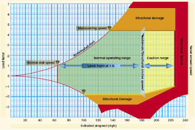
Load Factors
Load factors are measured in G's. An increase in load factor results in an increase in stalling speed. Load Factor Categories are as follows:
Normal: 3.8 to -1.52 Gs
Utility: 4.4 to -1.76 Gs
Acrobatic: 6.0 to -3.00 Gs
Not surprisingly, increase in angle of bank increases load factor due to Centrifugal Force and the increased back pressure required to maintain altitude. When load factor is squared, stalling speed doubles.
Maneuvering Speed (VA) = Highest speed the plane can fly and have complete control deflection without structural damage. ie: plane will stall before damage can occur.
High Speed Flight
At speeds of about 260kts, air is considered incompressible (its density remains nearly constant while pressure varies). At high speeds, compressibility results in shock wave formation, drag increase, buffeting, and control difficulties because air is now accelerating at sonic speeds.
Critical Mach - Mach 1.0 is the transition from subsonic to transonic flows.
Compressibility effects occur when approaching critical mach because the air ahead of the aircraft is no longer "warned" of its arrival. These air molecules become disrupted violently changing their pressure and temperature. Immediately after the plane's passage, the air pressure increases, and subsequently drag increases.
Shock Waves - a factor in increase in drag can be delayed through the use of Sweepback. Airflow hits the wing at an angle less than 90º resulting in the wing believing it is flying slower than it actually is. Swept wings stall at tips before roots, however because the tip is behind the Center of Lift.
Sunday, July 29, 2012
Aeromedical Factors
Aeromedical Factors Notes:
Pilot Personal Checklist -
I - Illness
M - Medications
S - Stress
A - Alcohol
F - Fatigue
E - Emotion
Obtaining a Medical Certificate -
Medicals acquired by Aviation Medical Examiner (AME). There is a directory of these examiners kept at FSDOs and other FAA offices. A student pilot receives a combined student pilot certificate and medical. 3 Classes of medical - each with different privileges and requirements (14 CFR Part 67/61).
•3rd Class - valid for Private/Recreational pilots. If under 40, valid for 3 years. Over 40, valid for 2.
•2nd Class - for commercial pilots. Valid for 1 year.
•1st Class - for ATP pilots, valid for 6 mos.
Physical Limitations / Conditions & Solutions
Depending on situation, certain equipment may need to be installed on aircraft to aid in pilots with disabilities. Others may require limitations upon the certificate itself. If pilot can demonstrate that they can safely operate an aircraft, a Statement of Demonstrated Ability may be issued (SODA). Details at http://www.faa.gov/about/office_org/headquarters_offices/avs/offices/aam/ame/guide/app_process/general/appeals/soda/.
Health / Physiological Factors
•Hypoxia - lack of oxygen in either blood, brain, or lungs.
Symptoms - Cyanosis, headache, drowsiness, dizziness, euphoria, tunnel vision.
Remedy - Descend promptly, use supplemental oxygen, turn off Cabin Heat
There are 4 Types of Hypoxia - Hypoxic, Hypemic, Stagnant, and Histotoxic
Hypoxic - Insufficient oxygen in body as a whole. Flying at high altitudes is common culprit. While percentage of oxygen at altitude remains the same, its pressure is reduced (fewer molecules to breathe).
Hypemic - Blood is unable to transport oxygen. Common culprit is CO2 poisoning. Could also be result of anemia or donating blood.
Stagnant - Blood has oxygen, but isn't moving. Can result from G-forces or cold temperatures.
Histotoxic - Cells have received the oxygen, but unable to use it. This impairment is caused by alcohol and other drugs.
•Hyperventilation - Excessive rate and depth of respiration leading to abnormal loss of CO2 from the blood. Often caused by stressful situation.
Symptoms - Rapid breathing, unconsciousness, visual impairment, tingling, muscle spasms
Remedy - Breathe into paper bag and consciously concentrate on slowing breathing.
•Middle Ear/Sinus Problems - During climbs and descents, free gas expands due to difference in pressure within body and outside. If gas cannot escape readily, pressure builds up and causes pain.
In middle ear, Eustacian Tube allows pressures inside middle ear and outside to equalize. In climb, tube expands. In descent, in constricts causing discomfort. This is hampered more by sinusitis or a cold. Decongestants may help, but should be verified safe by an AME.
•Spatial Disorientation / Illusions - Pilot's lack of orientation regarding movement of airplane, position, and attitude. Body uses 3 systems to sense its position in space.
1) Vestibular - organs in inner ear - sense of balance
2) Somatosensory - nerves in skin, muscles, and joints - sense position based on gravity and feeling
3) Visual - eyes which sense position based on what they see
In Visual flight conditions, pilots typically depend on visual cues, which are often able to correct for false senses from the other physical sources. Difficulties are often encountered when flying on instruments.
Vestibular system is easily tricked. The inner ear contains canals with fluid and tiny hairs. These sense motion. For example, a climb causes these hairs to move back, but so does acceleration. These two sensations could be confused if unable to see outside the plane. Furthermore, a maneuver that is well coordinated and slow may not cause any sensation in the inner ear. This could result in a pilot entering a graveyard spiral when they attempt to climb (they are actually tightening spiral). The best remedy is to rely on instruments.
Visual illusions - pertain mostly to false horizons or obscured horizons. This can occur if there is sloping terrain or a haze that obscures the actual horizon. These are especially acute at night when there is less to see. Autokinesis is another night-flying concern as staring at a stationary light will cause it to move about.
Furthermore, runways themselves can be illusions. Upsloping or narrow runways, for example, give pilots the illusion that they are too high - resulting in a lower than normal approach. Rely on VASI and PAPI indicators if available and become familiar with runway lengths and widths prior to landing.
•Motion Sickness stems from the brain receiving conflicting messages about the body. The inner ear is being over-stimulated Anxiety/stress can contribute.
Symptoms include nausea, dizziness, paleness, dry mouth, and sweating.
Remedies include landing promptly, opening air vents, loosening clothing, instructing sufferer to focus on the horizon.
•Carbon Monoxide Poisoning is essentially a form of hypoxia (hypemic). This is mostly triggered by aircraft cabin heating systems which redirect heat from the manifold exhaust shroud to the cabin. If there is a crack in the manifold, poisonous exhaust gases may enter the cabin.
Symptoms include drowsiness, blurred vision, headache, dizziness.
Remedies include turning off cabin heat, opening air vents, descending rapidly.
•Stress is often difficult to diagnose and treat because it can be heavily internalized. However, each pilot should be able to recognize the stress factors in their life and how they could jeopardize the safety of the flight. Ultimately, the pilot does not want to be distracted. A pilot experiencing a recent bad breakup with a significant other or death in the family should not fly.
•Fatigue like stress may seem benign, particularly because pilots often face demanding schedules. A fatigued pilot has slower reaction times and has less concentration. Again, if the pilot is so fatigued, that they become distracted from their primary duties, they should not be flying. Only more rest can correct fatigue. Red Bull and coffee are not solutions.
•Dehydration is a lack of water in the body. This can occur on hot days, or consumption of caffeinated drinks. The body experiences fatigue and headache. Bring water on board - even on short flights.
Alcohol/Limitations
Alcohol impairs the body at sea level. With an increase an altitude, these effects are magnified. Even a small amount can reduce reaction time, impair vision, and impair judgement. Pilots must not drink within 8 hours before a flight and cannot have more than .04% alcohol in their system. (14 CFR Part 91). Common sense should step in. Even if your flight is more than 8 hours away the following morning, drinking the night before is not wise. A hangover is just as damaging to pilot judgement and makes flying an unpleasant experience for all involved.
Drugs
While we often think of illegal narcotics as being hazardous, even over-the-counter medications can pose a risk. Almost all drugs have side effects, which could become more pronounced at altitude. Something like Tylenol is not of great concern, stronger pain killers could cause mental confusion and nausea. This is obviously not safe for flying. If you are unsure of the safe use of medication and flying, consult an AME.
SCUBA / Decompression concerns
When SCUBA diving, an excess nitrogen remains in the system. If the body enters a state of low pressure too soon, this gas forms bubbles, which is not only extremely painful, but can be fatal. The best remedy for this is time to allow the gas to dissolve completely prior to flying. In most cases, wait 24 hours. If there was not a controlled ascent and you are flying less than 8,000 ft, 12 hours is deemed sufficient. Although airlines are pressurized for 6-8,000 ft, you cannot rely on them being pressurized the entire time. A sudden decompression would be extremely hazardous to someone who did not allow enough time after SCUBA.
Vision
Particularly in Visual flight conditions, eyes are extremely important. Its main light-sensitive components are Rods and Cones.
Cones - are responsible for all color vision and are located near the center of the field of vision.
Rods- are better for detecting motion and are better suited for low light. Therefore, during the day, cones are better suited for looking for traffic, and at night Rods are more effective. Rods do, however, take longer to adjust because they are so sensitive to light. This is why pilots must wait at least 30 mins. for their eyes to adjust to the darkness after looking at a bright light.
Subscribe to:
Posts (Atom)